Optical Smoke Det Activ En54-7 Wiring Diagram / Iso 9001:2008 optical smoke detector model:. Iso 9001:2008 optical smoke detector model: In the circuit diagram the led and buzzer are connected in parallel. If not observed, there is a risk of electric shock hazard. Two wires on the both h pins, one wire on one of the a pins (any) and another on any of the b pins. So the relay is energised continuously till the initial input condition (no smoke).
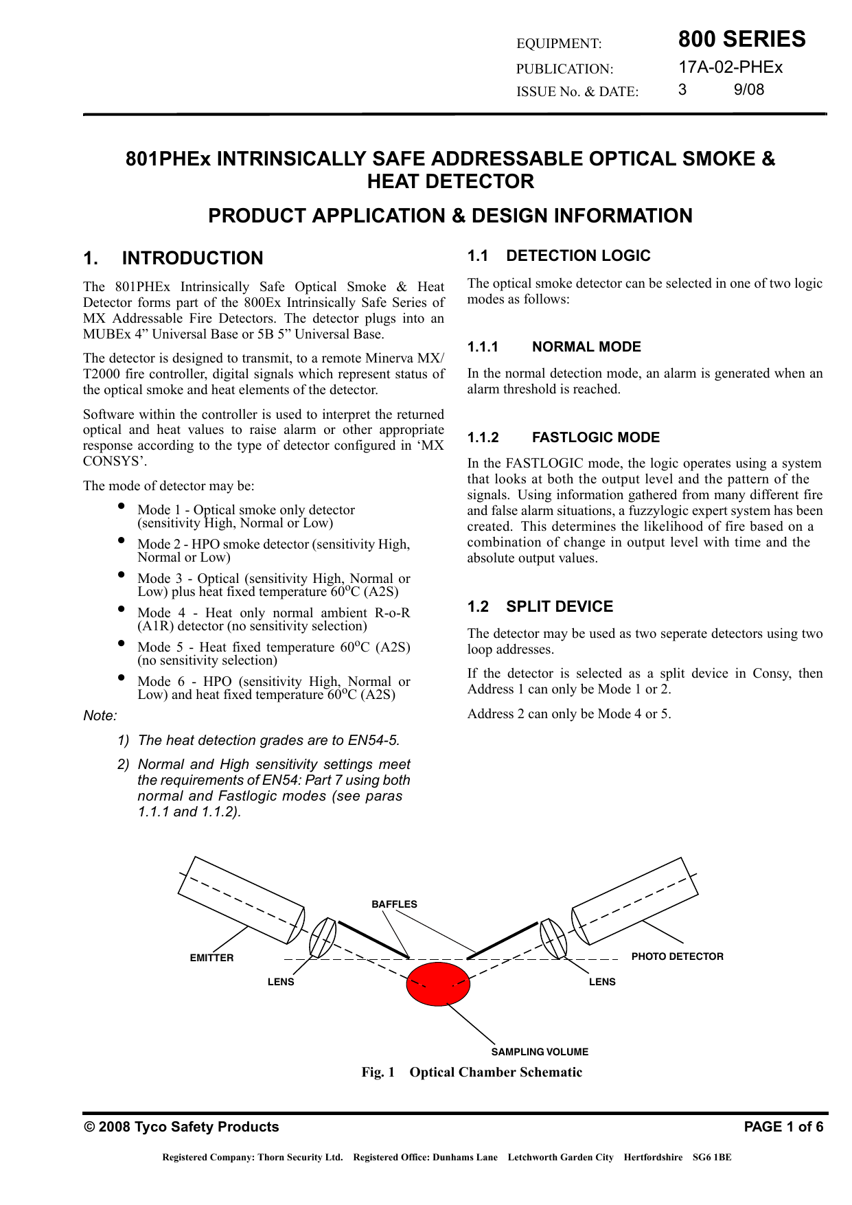
The lens is used to focus the light onto the first incident. Ensure that the plant cannot be inadvertently switched on again and that it is indeed dead. On the rear of all photain heat detector data sheets, a diagram showing the relevant coverage they provide is shown. Solder 4 wire onto the sensor. An optical smoke detector is a device that senses smoke, typically as an indication of fire.
St P Om Optical Smoke Detector 12 24v Manualzz from s2.manualzz.com In this circuit, we have used an mq2/mq6 smoke or gas sensor module for detect smoke present in the air. Solder 4 wire onto the sensor. This home smoke detector circuit warns the user against fire accidents. This type of circuit is called optical smoke detector. Lifeco fire alarm.panel wiring diagram gst 5000 fire alarm panel gst addressable smoke detector wiring diagram. A remote indicator can also be connected. The lens is used to focus the light onto the first incident. Whenever smoke is detected by the smoke sensor, the buzzer and led should work.
Solder 4 wire onto the sensor.
Do not use it as a home smoke detector the simple schematic diagram of a smoke detector presented here utilizes the gas sensor. Solder 4 wire onto the sensor. If remote indicator is not used. A remote indicator can also be connected. 5 en54 listed compatible control panel eol last detector base resistor led detector head opening here 6 1 3 4 6 1 3 4 remote indicator base class a optional wiring note: On the rear of all photain heat detector data sheets, a diagram showing the relevant coverage they provide is shown. An optical smoke detector is a device that senses smoke, typically as an indication of fire. The lens is used to focus the light onto the first incident. Lifeco fire alarm.panel wiring diagram gst 5000 fire alarm panel gst addressable smoke detector wiring diagram. Wireless connectivity, audio and multiple sensing (temp, humidity and motion) are new trends in smoke and heat detectors. show full abstract knowledgeable electrcians. If not observed, there is a risk of electric shock hazard. Our integrated circuits and reference designs help you solve challenges from emerging standards and technologies such as photoelectric, ionization, and heat/co detection.
From the arduino board, i'm only controlling the smoke sensor. This instructable explains how to make a simple smoke detector using and arduino and a carbon monoxide sensor. 5.4 the wiring diagram for detectors to control panels is shown in figure 2. Related searches for en54 7 smoke detector: It is also capable of providing detailed wiring diagrams of the system terminals in accordance with the configured settings.
17a 02 Phex 801phex Iss3 Fm Manualzz from s3.manualzz.com On the rear of all photain heat detector data sheets, a diagram showing the relevant coverage they provide is shown. So the relay is energised continuously till the initial input condition (no smoke). show full abstract knowledgeable electrcians. Optical smoke detector is a project implemented on the arduino board and works on the phenomenon of light scatter principle. Circuit diagram of this smoke detector project is given below: Oil level detective temp sensor error. The smoke chamber using the principle of. 5 en54 listed compatible control panel eol last detector base resistor led detector head opening here 6 1 3 4 6 1 3 4 remote indicator base class a optional wiring note:
If not observed, there is a risk of electric shock hazard.
A remote indicator can also be connected. Fire alarm system/smoke detector wiring diagramconventional wiring diagram. C4416 detector is en54 certified and ideal for use on any conventional fire alarm systems. On the rear of all photain heat detector data sheets, a diagram showing the relevant coverage they provide is shown. 5.4 the wiring diagram for detectors to control panels is shown in figure 2. Circuit diagram of this smoke detector project is given below: Ensure that the plant cannot be inadvertently switched on again and that it is indeed dead. The smoke chamber using the principle of. An active end of line module (hrmodule) could be wired to the end of the zone/s in place of the normal end of line unit. The lens is used to focus the light onto the first incident. Whenever smoke is detected by the smoke sensor, the buzzer and led should work. So the relay is energised continuously till the initial input condition (no smoke). 4.2.2 the optical smoke detection shall be designed in accordance with the functional requirements of en 54 part 7.
4.2.2 the optical smoke detection shall be designed in accordance with the functional requirements of en 54 part 7. Do not use it as a home smoke detector the simple schematic diagram of a smoke detector presented here utilizes the gas sensor. Oil level detective temp sensor error. Wireless connectivity, audio and multiple sensing (temp, humidity and motion) are new trends in smoke and heat detectors. Ensure that the plant cannot be inadvertently switched on again and that it is indeed dead.
Https Www Notifierfiresystems Co Uk Docs Notifierfiresystems En Gd Notifier 20little 20black 20book 202014 Pdf from From the arduino board, i'm only controlling the smoke sensor. This type of circuit is called optical smoke detector. Two wires on the both h pins, one wire on one of the a pins (any) and another on any of the b pins. Whenever smoke is detected by the smoke sensor, the buzzer and led should work. Our integrated circuits and reference designs help you solve challenges from emerging standards and technologies such as photoelectric, ionization, and heat/co detection. A remote indicator can also be connected. The smoke chamber using the principle of. Do not use it as a home smoke detector the simple schematic diagram of a smoke detector presented here utilizes the gas sensor.
This type of circuit is called optical smoke detector.
Optical smoke detector is a project implemented on the arduino board and works on the phenomenon of light scatter principle. It is also capable of providing detailed wiring diagrams of the system terminals in accordance with the configured settings. show full abstract knowledgeable electrcians. This home smoke detector circuit warns the user against fire accidents. 5.4 the wiring diagram for detectors to control panels is shown in figure 2. Our integrated circuits and reference designs help you solve challenges from emerging standards and technologies such as photoelectric, ionization, and heat/co detection. Wireless connectivity, audio and multiple sensing (temp, humidity and motion) are new trends in smoke and heat detectors. Solder 4 wire onto the sensor. An optical smoke detector is a device that senses smoke, typically as an indication of fire. 4.2.2 the optical smoke detection shall be designed in accordance with the functional requirements of en 54 part 7. A remote indicator can also be connected. Section one specification for a digital addressable fire system. Two wires on the both h pins, one wire on one of the a pins (any) and another on any of the b pins.


0 Comments